Permitted wharf · Southwestern Nova Scotia · Planning snapshot 2026-08-10

Build the piles DIY-first. Escalate only when the bottom makes you.

A cost-first installation sequence for a roughly 12 × 100 ft fixed timber-pile wharf using your Wacker Neuson 3.5-ton excavator. The machine can do substantial preparation and may run a compact pile driver—but it should earn the production-driving role through controlled test piles.

1st choiceCompact clamping vibro test
2nd toolHydraulic auger / probe
FallbackOne hired piling mobilization
Big constraintSafe access to 100 ft offshore
Bottom line

What I would do

Confirmed preliminary pile concept

10-in nominal diameter × 20-ft overall length × 6-ft target seabed penetration.

This geometry leaves approximately 14 ft from seabed to pile top. Confirm whether “10 in” means minimum tip, nominal/average shaft, or butt diameter—a structural marine pile is normally tapered and specified by tip and butt dimensions, species, grade and treatment.

254 mm nominal6.10 m overall1.83 m embedment target
What those dimensions mean

The pile is outside the published 8-in limit of the compact Midi Postmaster. Its manufacturer lists the 10-in Maxi model for a 5–8-ton carrier, so the likely 3.5-ton Wacker is not a demonstrated match.

The 6-ft penetration is a preliminary target—not evidence by itself of compression, uplift, lateral, ice, wave, scour or settlement capacity.

Use a hybrid strategy. One method is unlikely to work over the whole 100-ft alignment. Do the probing, material handling, access preparation, pile template, temporary bracing, framing and decking yourself. Rent or source a compact clamping vibratory driver for a small test program through penetrable overburden. Where the engineer requires it, finish or verify seating with controlled purpose-built impact equipment. At hard refusal, stop and investigate—do not simply hit the timber harder.

This preserves the maximum sensible DIY savings without gambling the wharf on a 3.5-ton machine that may be limited by attachment mass, pile handling, difficult bottom layers or offshore reach.

Ranked low-cost → specialist

The order I would pursue

1

Owner preparation and bottom reconnaissance

Lowest cost · highest DIY value

Lay out the approved alignment, record water and bottom elevations, probe representative pile positions, prepare shore access or approved staging, fabricate a reusable positioning template, and procure only enough certified marine timber for the test phase.

2

Compact hydraulic vibro test on actual pile material

Best first installation experiment

Match a clamping vibratory driver to the exact excavator circuit, pile diameter, pile weight and working radius. Test nearshore, mid-length and outer-bottom conditions if the approved access method permits. Record penetration versus time, obstructions, plumbness and pile damage.

3

Add a hydraulic auger or controlled pilot method

Use selectively—not automatically

Where permitted and accepted by the engineer, use a narrow pilot hole to get through a localized shell or dense gravel lens. Do not assume a large loose hole around the pile provides the required lateral or axial support.

4

DIY all preparation; hire one production piling mobilization

Most reliable cost-controlled fallback

Have every pile, template, staging component and layout point ready before the contractor arrives. Let the specialist bring the larger carrier, barge/spud platform and hammer needed to install and document the piles efficiently; then resume the framing, bracing and decking yourself.

5

Revisit the outer geometry if access dominates cost

Design alternative, not an improvised field change

If reaching 100 ft offshore requires disproportionately expensive marine plant, ask the designer and permit authorities whether an approved shorter fixed approach plus floating outer section is viable. Do not change the permitted configuration without approval.

No-barge possibility

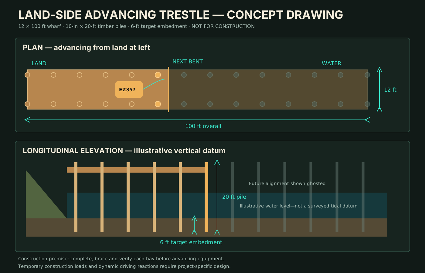
Advance from land—one complete, braced bay at a time

Credible cost-saving possibility: install the first bent from shore, complete its cap, longitudinal members, temporary bracing and construction deck, then use that verified platform to install the next bent. Repeat outward. This can eliminate a piling-barge mobilization if the bottom remains drivable and the temporary structure is designed for every construction stage.

Establish the land-side launch bay

Prepare stable access and install enough nearshore piles, caps and bracing to create the first engineered work platform.

Feed one pile along the completed deck

Keep pile stock and heavy attachments back from the active edge. Move one pile forward horizontally using rated supports, rollers or rigging—never workers beneath a suspended pile.

Pitch and drive the next bent

Use a positioning template and properly matched clamp/driver. The 20-ft pile, attachment and real working radius must fit the machine lift chart throughout horizontal handling, pitching and driving.

Cap, brace and verify before moving

Survey the new piles, install temporary and permanent bracing, and obtain the required installation acceptance before extending the construction deck or advancing the machine.

Maintain a planned escape route

Material flow, hydraulic hoses, tide windows and machine travel must never block retreat to land. Do not advance onto a partially framed or unverified bay.

What this may save

  • Barge transport and marine mobilization
  • Repeated contractor mobilizations
  • Floating-plant positioning time
  • Some offshore material handling

What it does not eliminate

  • Construction-stage structural design
  • Driver and carrier compatibility
  • Safe 20-ft pile-pitching geometry
  • Test-pile and installation records
  • Specialist fallback for cobbles, rock or early refusal
Critical gate: the final pedestrian wharf capacity does not automatically prove that each incomplete stage can support an excavator, stored pile, attachment and dynamic driving reaction. The temporary load path and allowable machine position must be checked before construction begins.

Open the interactive land-side 3-D construction model →   Plan/elevation drawing ↗   Parametric OpenSCAD model ↗   Complete package (.zip) ↗

Attachment shortlist

Hydraulic tools worth investigating

#1

Clamping vibratory post driver

Grips the timber, controls it while vibrating, and can often extract or reposition it. Best prospect in mud, sand, shell and loose-to-moderate granular material.

The compact benchmark is now ruled out: the Midi Postmaster is limited to 8-in posts. The same manufacturer’s 10-in Maxi requires 45–60 L/min at 200 bar and a 5–8-ton carrier. That is evidence to investigate a larger carrier—not approval for the EZ35/EZ36.

Primary test toolLarger carrier indicated
Manufacturer literature ↗
#2

Hydraulic auger / rock-earth bit

Useful for reconnaissance and localized pilot holes. Published 3–5-ton auger drives commonly span roughly 10–30 GPM depending on model and can accept earth or combination rock/earth tooling.

Not a capacity shortcut: pilot-hole diameter, depth and final undisturbed driving must follow the engineer’s installation criteria.

Obstacle toolProbe tool
Digga 3–5 t specifications ↗
#3

Purpose-built hydraulic impact driver

Controlled impact may be needed to finish seating or verify the engineer’s driving criterion after vibration. Many compact products are designed for fence-sized posts—not engineered marine timber piles—so cup/helmet fit, cushion and driving energy must be checked.

Reject a homemade hanging drop weight. FHWA describes drop hammers as slow, difficult to control and at high risk of overstressing foundation piles. Use guided, purpose-built equipment with a pile helmet if impact is required.

Possible verification toolProtect pile head
FHWA driven-pile guidance ↗
#4

Water jetting

Potentially effective in sand, but much less attractive in clay or coarse gravel. Technical guidance calls for very large water flow and warns that jetting can loosen soil around nearby piles; final penetration normally requires driving.

This is not the cheap pressure-washer shortcut it first appears to be, and it must be explicitly compatible with permit and environmental conditions.

Soil-specificEngineer-controlled
UFC jetting guidance ↗
Carrier gate

Your Wacker Neuson: confirm the badge before renting

Model ambiguity: “EZ 3.5” sounds like the 3.5-ton Wacker class, but the exact badge may be EZ35, EZ36 or ET35. The new North American EZ35 was announced for later in 2026. Existing EZ36/ET35 data must not be copied onto it without checking the data plate and manual.

What published EZ36/ET35 data suggests

Wacker Neuson publishes 240 bar system pressure and 120 L/min maximum total flow for current EZ36/ET35 models. That is not the same as available auxiliary flow at the stick couplers. Configuration options include adjustable AUX I and, on some versions, an enlarged unpressurized return.

Official EZ36 technical data ↗

What determines actual compatibility

  • Exact model, year and serial range
  • AUX I measured flow at operating RPM
  • Relief-pressure setting
  • Two-way circuit versus pressure-free return
  • Maximum permitted return pressure and case drain
  • Coupler type, hose size and bracket
  • Continuous-duty suitability and oil cooling
  • Attachment + adapter + pile weight at real radius
  • Lift chart, blade orientation, track support and slope
Photograph the model/serial data plate
Photograph both stick-side hydraulic couplers
Photograph cab AUX controls/settings screen
Find the configuration-specific lift chart
Record pile diameter, length and estimated weight
Tell supplier the maximum working radius
Working conclusion: treat the 3.5-ton Wacker as a support/test machine, not the assumed production pile driver. A uniform 10-in × 20-ft wood cylinder is about 10.9 ft³; depending on species, moisture and treatment it can already approach roughly 400–600 lb. Real structural piling is tapered: one representative 20-ft treated pile listing gives 600–800 lb. Add the driver, coupler, adapter and hoses, then check the exact lift chart at the real radius. The 20-ft handling geometry and dynamic driving loads make a paper hydraulic-flow match insufficient. The outer wharf also requires an engineered advancing platform, stable intertidal access, or positively positioned floating plant.
Mixed seabed strategy

Change tools when the bottom changes

Observed materialFirst attemptIf penetration slowsDo not assume
Mud / soft sedimentClamping vibro with template controlContinue to specified penetration/acceptance layerEasy penetration equals adequate capacity
Sand / shellClamping vibroControlled pilot or approved jet assistance may helpJetting alone proves final capacity
Loose gravelVibro testSmall pilot/rock-earth auger if permittedAll gravel will behave alike
Dense gravel / cobblesProbe and one controlled testMove within approved tolerance or escalate to heavier piling plantMore excavator down-pressure is safe
Boulder / possible rockStop and characterize obstructionEngineer chooses relocation, socketing, drilling or revised foundation detailSudden refusal equals bearing acceptance
Spend a little before spending a lot

Test-pile sequence

Before starting

  1. Confirm permitted access and installation method.
  2. Obtain engineer-defined embedment, refusal and acceptance criteria.
  3. Choose actual pile species, grade, treatment, diameter and tip.
  4. Confirm attachment and carrier compatibility in writing.
  5. Build a rigid reusable alignment/template frame.

Record for each pile

  • Location and bottom elevation
  • Pile length, diameter and treatment ID
  • Tool, settings and operating time
  • Penetration versus time or impact count
  • Obstruction depth and response
  • Final cut-off elevation and plumbness
  • Visible pile-head or shaft damage

GO

Pile remains controlled and plumb, reaches the specified installation criteria, and the machine stays stable within its lift chart. Repeatability is demonstrated across representative locations.

PAUSE / ADAPT

Localized shell or gravel lens slows installation, but probing supports an approved pilot method. Test the modified procedure on one pile before production.

STOP / ESCALATE

Machine becomes unstable, attachment exceeds return limits, pile cannot be safely handled, refusal is irregular, timber is damaged, or the criteria cannot be demonstrated.

Timber and worksite protection

Protect the pile—and know when to stop

Marine timber specification

  • Request round marine piles documented for CSA O80 UC5A brackish/saltwater and adjacent-mud exposure.
  • Obtain species, grade, butt/tip dimensions, preservative, penetration/retention and treatment certification.
  • Use a square concentric head, close-fitting helmet/cushion and engineer-specified head band or toe protection for hard driving.
  • Field-treat cuts, bolt holes and damage; collect treated-wood waste away from the water.
Wood Preservation Canada pile guide ↗

Immediate stop conditions

  • Machine rocking, track settlement or changing barge trim
  • Clamp movement, hydraulic leaks or hose damage
  • Pile bowing, splitting, brooming or abrupt deflection
  • Irregular hard refusal or unexplained resistance change
  • Loss of clear communication, safe egress or tide/weather margin
  • Uncontrolled turbidity or sediment discharge
Nova Scotia safety regulations ↗
Protect the savings

DIY the work that pays; hire the risk that does not

Strong owner-build scope

  • Access and staging preparation within permit conditions
  • Bottom probing and organized test records
  • Marine-pile procurement and delivery planning
  • Pile template, guides and temporary bracing
  • Material handling within the machine’s rated capacity
  • Caps, beams, permanent bracing and decking after acceptance

Keep technical checkpoints

  • Structural pile size, spacing and bracing design
  • Geotechnical installation/acceptance criteria
  • Obstruction, refusal and rock-socket decisions
  • Marine platform, barge or causeway stability
  • Any change from the permitted footprint/method
  • Production driving when compact equipment cannot prove acceptance
The cost-control idea: do not hire a contractor to discover that the site is not ready. If specialist piling is needed, have the piles delivered, template built, positions marked, access prepared and decisions pre-agreed. Pay for one efficient mobilization—not repeated troubleshooting visits.
Reference set

Sources and limits

  1. Postmaster compact vibratory driver specifications.
  2. Premier compact impact post-driver specifications.
  3. Digga 3–5-ton excavator auger-drive specifications.
  4. Wacker Neuson EZ36 technical data.
  5. North American EZ35 introduction and availability.
  6. UFC pile jetting methods and limitations.
  7. Pile Buck overview of vibratory, impact, hydraulic and jetting equipment.
  8. FHWA Design and Construction of Driven Pile Foundations, Volume II.
  9. UFGS Timber Piles installation specification.
  10. UFC Design: Piers and Wharves.
  11. Wood Preservation Canada 2025 round and sawn pile guide.
  12. Nova Scotia Occupational Safety General Regulations.
  13. Blue Diamond Series 2 driver and 10-in adapter data—a product lead only; not proof of structural marine-pile or carrier suitability.
  14. Representative 20-ft treated piling dimensions and 600–800-lb listed weight—use the project supplier’s certified dimensions and weight.

Planning limit: this page orders methods and decision gates; it is not the wharf’s structural or geotechnical design. The owner’s preliminary 10-in × 20-ft pile and 6-ft penetration target are recorded, but tip/butt dimensions, pile spacing, pile count and acceptance criteria still require supplier data and project design confirmation.